Monday, December 20, 2010

How to expand an A- SIS enabled volume that is nearing the "vol size" limit

WARNING: If this is being performed to free up space to bring a LUN back online, another method of cleaning up space should be considered, such as deleting snapshots and disabling automatic snapshots until a maintenance window can be scheduled as the 'undo' process can take a significant amount of time.

To increase the size of an A-SIS enabled volume beyond the maximum limit for A-SIS, the A-SIS service must be turned off and the changes undone. Undoing A-SIS will re-inflate the file system and could require more disk space than is available in the A-SIS enabled volume. There is no way to expand the volume size until the undo is completed, so the recommended course of action is to create and use a temporary volume and migrate data necessary to free enough space for the re-inflation to complete.
WARNING: Once the volume is grown beyond the maximum size supported for A-SIS, A-SIS will be disabled.

WARNING: Disabling A-SIS will require additional disk space as files will be undeduplicated.

WARNING: Using "sis undo" may require rebaselining of snapmirror or snapvault relationships.

Complete the following steps to undo A-SIS:


Note: The undo must be performed from diag mode. The sis undo command can take some time (hours) based on how much data is being un-deduped and the filer type.

1- Enter df -s
Note the space saved, this is the amount of space that will be necessary for the re-inflation.
2 - Enter df
Note the available space. If it is not greater than or equal to the space saved found in the previous output, space will need to be cleared using other methods to complete the undo (e.g., deleting Snapshots or migrating data).
3 - Enter sis off
4 - Enter priv set diag
5 - Enter sis undo


Once the undo is complete, the volume will be a normal FlexVol volume that can be expanded.

When trying to access the filer using a NetBIOS alias, error message: Decrypt integrity check failed

When trying to access the filer's NetBIOS alias, the following error messages are generated:


[auth.trace.authenticateUser.krbReject:info]: AUTH: Login attempt from 10.20.1.13 rejected by Kerberos.
[cifs.trace.GSSinfo:info]: AUTH: notice- Could not authenticate user.
[cifs.trace.GSSinfo:info]: AUTH: notice- Decrypt integrity check failed.


Issue
The Active Directory had a stale computer account that had the same name as the NetBIOS alias used to contact the filer. The NetBIOS alias may have been created in the Active Directory during vFiler testing, but the account had not been removed.


Check the following:
1. Check for another account in the same AD forest that has the same name as the filer. This can either be a stale account (left over from a previous situation), or another machine.


2. The reason you can connect when you specify an IP address is that the client uses NTLM instead of Kerberos in that situation. When the client gets a Kerberos ticket, it is most likely getting a ticket for the wrong machine.


Friday, December 3, 2010

How to Reboot / Reset an HP Blade iLO2

Every once and awhile an iLO2 Remote Control session will get "stuck". By this I mean when you try to connect, it will say that there is a session already in progress. A reboot of the iLO2 will clear this state. To restart the iLO2, follow these steps.

* From the Web Administration page for the iLO2, you should be on the System Status tab by default 
* Click Diagnostics on the left hand side
* On the bottom of this page is a Reset button for the iLO2

Sunday, October 17, 2010

Moving the Root Volume in NetApp

When you move the root volume you need to do the following:

* Create a new aggregate on the array for that root volume.
* Copy the root volume to the new aggregate.
* Destroy the original root volume and its containing aggregate.
* Check th eInstallation Requirements, Quick Start, and Reference Guide to determine the minimum root volume size for your system model.


Steps:
1. Check the output from sysconfig -r to ensure that adequate size for the root volume is available on the storage array where you want the root volume.

2. Create a new aggregate for the new root volume. This command creates an aggregate to contain a FlexVol root volume:
cherry-top# aggr create aggr_new -r 14 -T FCAL -r raid_dp -d 0a.23 0a.24 0a.25

3. Create a FlexVol for the root volume:
cherry-top# vol create vol0_new aggr_new -s 30g

4. Vol copy or ndmpcopy to copy the root volume to the new root volume:
yellow# ndmpcopy /vol/vol0 /vol/vol0_new
if its a volcopy then restrict it to prevent data access while you are moving the root volume:
cherry-top# vol restrict vol0_new

5. Specify that the volume named volroot will become the root volume after the next reboot:
cherry-top# vol options vol0_new root

6. Reboot the system and check the system integrity:
cherry-top# reboot


7. Check the system to ensure vol options
cherry-top# vol status


8. Offline/destroy the original root volume and destroy the aggregate
cherry-top# vol offline vol0
cherry-top# vol destroy vol0
cherry-top# aggr offline aggr_old
cherry-top# aggr destroy aggr_old

Sunday, October 10, 2010

Error message: Ndmpcopy: Authentication failed for source

There are several reasons for ndmpcopy to fail:

•The password for both the source and destination filer are not given:
ndmpcopy -sa root: -da root: filer1:/vol1 filer:/vol1

•Authentication depending on the authentication type: challenge or text. With Data ONTAP 6.1 and earlier, an authentication error will occur if ndmpcopy tries to authenticate using md5.

•The source pathname is invalid. The following is an output from the 'ndmpcopy' command when the source path name is invalid:

Solution:
1.Set the options ndmpd.authtype to "challenge" on the source and destination. Data ONTAP 6.1 and earlier versions require ndmpcopy authentication to be set to TEXT.

2.Find the encrypted password for a user, using the following command:
ndmpd password ndmpuser

Find the source password:
fas270cl1-ca-n2> ndmpd password ndmpuser
password RtafEaSBeZEP31ws

Find the destination password:
fas270cl1-ca-n1> ndmpd password ndmpuser
password bHzZT0u3VFnIAeKD

3.Now retry the NDMP copy, specifying the passwords on the host and destination filers:

ndmpcopy -sa root:[passwd] -da root:[passwd] filer1:/vol1 filer2:/vol1

Tuesday, August 24, 2010

EMC Centera/CAS/OBS

What is EMC Centera?

The EMC Centera is the world's first magnetic hard disk-based WORM data storage device, providing Write Once Read Many functionality to applications that require data to be stored on a non-rewriteable, non-erasable storage medium.

By using traditional magnetic hard disks as its storage medium, the EMC Centera offers greater performance over other archival media types such as optical and tape. EMC developed the Centera to address the storage of fixed content data, the fastest growing data type today.

What is Fixed Content Data?

Fixed content data is any digital asset that is created once, never modified, and must be retained for reference throughout its life cycle and retention period as required by regulatory agencies.

The recent explosion in the creation of fixed content has created a demand for a new category of storage devices designed to provide fast, secure on-line access to this data with long-term availability. The EMC Centera represents this new category of data storage devices known as Content Addressed Storage (CAS).

What is Content Addressed Storage?

Content Addressed Storage is a method of data storage that stores and retrieves a data object by its content address within the storage system, rather than by its actual file name at some physical location.

The benefit of a content addressable approach to storage is that an object is stored in such a way that it is authenticated and unalterable. In addition, objects cannot be deleted prior to the expiration of its defined retention period.


How Content Addressed Storage Works

When an application delivers a data object to the EMC Centera, the API calculates a 128-bit “claim check” that is uniquely derived from the objects binary representation. The metadata for the object, which includes filename, creation date, etc., is inserted into an XML file called a C-Clip Descriptor File (CDF), which in turn has its content address calculated. The Centera repository then stores the object and a mirror copy.

Once two copies of the object and CDF are stored in the repository, the Content Address is returned to the application. Future access to the data object occurs when the application submits the CDFs Content Address to the Centera repository via the API. The data is then returned back to the application. The Centera file system architecture eliminates directory structures, pathnames, and URL references to filenames and only uses the C-Clip Content Address as a reference.

How EMC Centera Provides WORM Functionality

The C-Clip Content Address of a data object assures the authenticity of that object. If an object is retrieved and altered, the Centera API produces a new CDF with a new content address for the altered object. The original object remains in its original form at its original content address and is still accessible by its original address.

This feature of Centera provides a level of versioning integrity that standard file servers and operating systems cannot provide. Additionally, Centera features an operational mode where an object cannot be deleted prior to the expiration date of a defined retention period. These non-rewriteable and non-erasable properties of the EMC Centera give the Write Once Read Many attributes required for compliance with SEC 17a-4, Sarbanes-Oxley, HIPAA, FDA, and many others.

Centera Hardware Architecture

Comprised of Redundant Arrays of Independent Nodes (RAIN), every node in a Centera contains a CPU, network interface, and 3TB of raw storage, and is interconnected with all other nodes in the cabinet via a private LAN. Each node executes an instance of CentraStar, the Centera operating software, in one of two operational modes to act as either a storage node or an access node.

The storage nodes provide the physical storage of data objects and C-Clip Descriptor Files and the access nodes provide the means for interaction between the application server and the storage nodes. Throughput and storage requirements of the application will determine how many access nodes vs. storage nodes must be configured at the time of installation of the EMC Centera.

Fault Tolerance

The EMC Centera is based around a “no single-point-of-failure” platform and can be serviced in a non-disruptive manner. Every component of the Centera has built-in redundancy. This includes hard drives, power supplies, AC power connectors, cooling fans, and network adapters and associated cable interconnects.

When drives fail, CentraStar, the Centera operating software, will transparently remove them from the cluster. Objects are regenerated from the current mirror to a new mirror to ensure that a fully redundant mirror copy of the content is always available. Data integrity checking runs in the background and continuously recalculates the content addresses of all the objects and compares the calculations to the content addresses originally stored in the C-Clip Descriptor File.
Scalability

A single Centera 19” rack cabinet can hold 8, 16, 24, or 32 nodes to provide 5.4TB – 43.2TB in mirrored mode, or 18.3TB – 73.4TB in parity-protected mode. For scalability beyond 73.4TB, multiple Centera cabinets can be configured as a single cluster, offering hundreds of Terabytes of total storage capacity in a single Centera storage pool.

When new storage units are added to the cluster and powered on, they are automatically “auto-discovered” and join the cluster. No reconfiguration or downtime is necessary to add capacity.

Wednesday, August 4, 2010

NetApp Telnet : Too many users logged in! Please try again later


You can log out the session blocking your log on attempt by running the following command.  
You can just execute the following command to remotely logout the user and free up the session.

rsh (hostname)  -l root:(password) logout telnet

Saturday, June 26, 2010

NetApp - Theory of Aggregate

NetApp's Aggregate is a DataONTAP feature that combines one or more Raid Groups(RG)  into a pool of disk space that can be used to create multiple volumes in different flavors. Newly added disks are assigned to the spare pool and a new aggregate or an existing aggregate that requires more space will then be pulled from the spare pool.


Unlike other Storage arrays where you create LUN from a specific RG, DataONTAP creates volumes within the available space in the aggregate across multiple RG. DataONTAP dynamically stripes the volumes across the aggregates within the Raid Groups. When disks are added to the aggregate they will either go into an existing RG that is not yet full or into a new RG if all the existing groups are full. By default RG are created as RAID-DP(dual parity drives) with stripes of 14+2 for FC/SAS disks and 12+2 for SATA disks. If you want to separate your "Vol0" in a separate aggregate, usually its aggr0 with a minimum of 3 disks for RAID-DP.

Aggregates have snapshots, snap reserve & snap schedule just like any other volumes. Aggregates may either be mirrored or unmirrored. A plex is a physical copy of the WAFL storage within the aggregate. A mirrored aggregate consists of two plexes;(A plex may be online or offline unmirrored aggregates contain a single plex. In order to create a mirrored aggregate, you must have a filer configuration that supports RAID-level mirroring. When mirroring is enabled on the filer, the spare disks are divided into two disk pools. When an aggregate is created, all of the disks in a single plex must come from the same disk pool, and the two plexes of a mirrored aggregate must consist of disks from separate pools, as this maximizes fault isolation.

An aggregate may be online, restricted, or offline. When an aggregate is offline, no read or write access is allowed. When an aggregate is restricted, certain operations are allowed (such as aggregate copy, parity recomputation or RAID reconstruction) but data access is not allowed. 

Creating an aggregate

Aggregate has a finite size of 16TB raw disk with 32 bit DataONTAP. By default, the filer fills up one RAID group with disks before starting another RAID group. Suppose an aggregate currently has one RAID group of 12 disks and its RAID group size is 14. If you add 5 disks to this aggregate, it will have one RAID group with 14 disks and another RAID group with 3 disks. The filer does not evenly distribute disks among RAID groups.

To create an aggregate called aggr1 with 4 disks 0a.10 0a.11 0a.12 0a.13 from a loop on fiber channel port 0a use the following command:

netapp> aggr create -d  0a.10 0a.11 0a.12 0a.13

Expanding an aggregate

To expand an aggregate called aggr1 with 4 new disks use the following command:

netapp> aggr add aggr1 -d  0a.11 0a.12 0a.13 0a.14

Destroying an aggregate

Aggregates can be destroyed but there are restrictions if volumes are bounded to the aggregate. Trying to destroy an aggr with volumes will throw an error but this can be overridden with the -f flag. It is recommended to go over each and every volume and destroying it before using the -f option to avoid any potential data loss. Aggregates can be destroyed much like any volumes but it needs to be taken offline.


To destroy an aggregate aggr1 use the following command:

netapp> aggr offline aggr1
netapp> aggr destroy aggr1

Friday, June 25, 2010

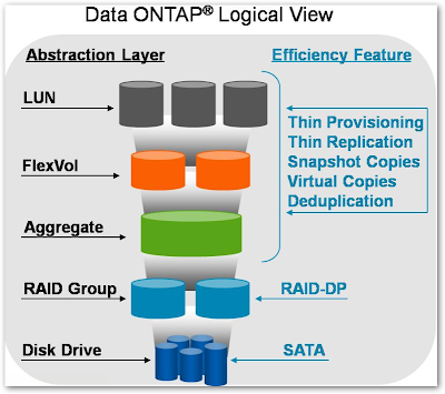
DataONTAP Logical View - LUNs, Deduplication, and Thin Provisioning

 This is one of the coolest storage model for NetApp that explains the placing of disks, Raid Groups, Aggregates, Flex Volumes, NAS and SAN. Thanks to Dr. Dedupe for sharing this piece of information. 

Sunday, June 20, 2010

NetApp Fractional Reserve

When we snapshot the filesystem, we take a copy of the file allocation tables and this locks the data blocks in place. Any new or changed data is written to a new location, and the changed blocks are preserved on disk.

This means that any new/changed blocks (D1 ) in the active file-system are written to a different location - this overwrite space is called as fractional reserve.

Fractional reserve ensures that there is space available for overwrites and the default fractional reserve space is 100% but this can be changed and generally set to "0" value.

So the reason a LUN will be switched offline if the fractional reservation area is set to 0, is that the filer needs to protect the existing data that is locked between the active file system and the most recent snapshot, plus any additional changes that happen to the active file system. If the volume / LUN / frac-res and snap reserve are full, then this space is not available and the filer needs to take action to prevent these writes from failing. The filers guarantee no data loss, but with no space free and no-where to write the new data, it has to offline the lun to prevent the writes from failing.

So fractional reservation is in constant use by the filer as an over-write area for the LUN. Without it, you need to make sure that sufficient space is free to allow for the maximum rate of change you would expect. Defaults are good, but trimming down on these you need to monitor the rate of change and make sure the worst case scenario is within a buffer of free space that you allow.

Pocket Survival Guide NetApp

Setting Up a Filer:
1. Check version and licenses
(telnet) license to list
(telnet) license add (key) to add a license
(FilerView) Filer -> Manage Licenses
2. Setup Network Interfaces (set up single-mode and multi-mode vifs or ifgrps)
NOTE: You can't modiy a vif once it is created. I usually have to delete the vif and start over to modify it. This also means network service will go down on that port group!
(telent) ifconfig -a to list the interfaces
(telnet) ifconfig command to manage the interfaces
(telent) To manage vifs in ONTAP 7: vif command, in ONTAP 8: ifgrp
(telnet) You can also run setup, will probably require a reboot!
(FilerView) Network -> Manage Interfaces -> i.e. vif1a or vif1b
3. Enable SSH on the filer
(telnet) secureadmin setup ssh
(FilerView) Secure Admin ->SSH -> Configure -> Generate Keys -> OK -> Apply
4. Set Snap reserve on Aggr0 if not MetroCluster
The default for this is 5%. I have seen some set this to 0% if not using MetroCluster. I set it to 3% because I have seen issues if set to 0% and NetApp support likes at least a little reserve at this level for disaster recovery
(telnet) snap reserve -A aggr0 3
(FilerView) I don't think this is possible from FilerView
5. Resize Vol0
(telnet) vol size vol0 15g for 2000 series (20gb on 3000 series)
(telnet) vol size vol0 to check
(FilerView) Volumes -> Manage -> Click on vol0
Click Resize Storage
Click Next -> Click Next -> Enter New Volume Size -> Next -> Commit -> Close
6. Iscsi & FCP status
(telnet) iscsi status to check
(telnet) iscsi start to enable
(telnet) same commands for fcp
(FilerView) LUNs -> Enable/Disable ->Check Enable Box
7. NTP Setup
(telnet) to list all time options: options timed
(telnet) options timed.servers 0.us.pool.ntp.org,1.us.pool.ntp.org,2.us.pool.ntp.org (or enter your time servers for your site)
(telnet) options timed.proto ntp (if not already set to ntp)
(telent) options timed.log on (if you would like the updates to go to console and log)
(telnet) options timed.enable on
(FilerView) Filer -> Set Date/Time -> Modify Date/Time
Choose Time Zone -> Click Next
Choose Automatic -> Click Next
Change Protocol to ntp -> Click Next
Enter ntp servers 0.us.pool.ntp.org (1&2) - or any other ntp server you have
Click Commit -> Click Close
8. Enable and Test Autosupport
(telnet) to list all options: options autosupport
(telnet) options autosupport.from (userid) - sets the userid autosupport is sent from
(telnet) options autosupport.mailhost (host ip or name)
(telnet) options autosupport.to (user1,user1)
(telnet) options autosupport.enable on
(telnet) options.autosupport.doit test - generates a test autosupport
(FilerView) Filer -> Configure Autosupport
Change Autosupport enabled to Yes
Enter mailhosts
Enter To: fields -> Click Apply
Click Test Autosupport on the left -> Click Send Mail
9. Check Cluster Failover
(telnet) cf status – Check Cluster Failover Status
(telnet) cf partner - Lists the partner head
(telent) cf monitor – more details on failover
(telnet) cf takeover - This will reboot the host you are taking over!
(telnet) cf giveback - when partner is ready to receive back
(FilerView) Cluster - Click the buttons! :)
10. Disk Commands (Assign Drives to Controller)
Typically I would assign the odd disks to the first controller and the evens to the second controller. I have also assigned the majority of drives to one controller and a minimum (3-4 drives) to the other controller to maximize capacity
(telnet) disk show –n - show disks NOT owned
(telnet) disk show –o (controller name) - show disks owned by a controller
(telnet) disk show –v - show all disks owned and not owned
(telnet) disk assign (drive#)
(telnet) disk remove_ownership (drive#) (This is a priv set advanced command!)
(telent) disk zero spares
(FilerView) - I don't think this is possible from FilerView
11. Aggregate Commands (Assign Drives to Aggregate)

In RAID-DP environments, if there are 2 hot spares, I often add one back in. You already have 2 drive failure with RAID-DP and this way you have one more drive capacity
(telnet) aggr status -v - shows status with volume information
(telnet) aggr status –r - shows which drives are in the aggr already including raid groups
(telnet) aggr options (aggr) - shows all options for the aggr (raid groups, raid type, etc.)
(telnet) aggr show_space -m OR -g
(telnet) aggr add (aggr) –d (drive#)
(FilerView) Aggregates -> Click on the aggregate
Click Show Raid to see existing disk configuration
Click Add Disks to add new disks and follow the wizard
12. Volume Commands (Create Volumes From Aggregates)

(telnet) vol status - shows all volumes and options
(telnet) vol create (volumename) -s none (aggr) (size) - create volume with no guarantee
(telnet) vol create (volumename) -s volume (aggr) (size) - create volume with volume guarantee
(telnet) vol size (volume) - check the volume size
(telnet) vol size (volume) (size) - set volume to new size
(telnet) vol autosize (volume) on - turn on volume autogrow, the volume will grow by default in 5% increments until 20% growth achieved by default
(telnet) vol autosize volume -m (new max size) -i (new increment amount) - notice that even though the defaults are 20% max and 5% increments, if you change the value the new values have to be in space (MB or GB)!
(telnet) vol autosize (volume) - reports the current setting
(telnet) vol options (volume) - list the volume options
(telnet) vol options (volume) guarantee volume OR none - sets the volume guarantee to volume or none
(telnet) vol options (volume) fractional_reserve (value) - sets fractional reserve to (value) but only works if volume guarantee is volume.
(telnet) vol options (volume) try_first snap_delete OR volume_grow - sets the value to which method a volume will use when it runs out of space. It will either grow the volume or delete snap shots. The defaults is to grow the volume.
(FilerView) Too much here to list. Just click on volumes and poke around. The following aren't possible in FilerView that I can tell: volume autosize, volume try_first option, changing fractional reserve
13. Check and Modify Snapshot Settings as Needed per Volume

NOTE: Disable the snapshot schedule on the volume if SnapManager is protecting the volume
(telnet) vol options (volume) nosnap on - Turn off the SnapShot Schedule but leave the schedule in place. I do this to disable snapshots in favor of the following command
(telnet) snap sched (volume) 0 0 0 - Disable SnapShots by modifying the schedule. I like the first option better.
(telnet) snap reserve (volume) (#) - Sets the snap reserve to #% of the volume
(telnet) snap autodelete (volume) - shows the snapshot autodelete settings
(telnet) snap autodelete (volume) on - turns on snapshot autodelete (Check the settings! Too many default settings to list here!)
(FilerView) Too much here to list. Just click on Volumes -> Snapshots and poke around. The snap autodelete option is not possible in FilerView that I can tell.
14. Set DeDupe Settings per Volume
DELETE EXISTING SNAPSHOTS FIRST ON THE TARGET VOLUME!
Note: For the sis command you need the full volume path, /vol/vol0 for instance
(telnet) sis on (full volume path) - enables dedupe on that volume
(telnet) sis start (full volume path) - runs dedupe on that volume now
(telnet) df –sh - To check space saving on DeDupe
(telnet) sis config and sis status to check settings
(telnet) sis config -s sun,mon-fri,sat@0,3-9,12 (full volume path) - The -s option allows you to change the schedule. You can list the days separated by commas or a range by dash, same with hours.
(FilerView) This is not possible in FilerView
15. Cifs setup (set up ntp first!)
(telnet) cifs setup
OR (Filer View) CIFS -> Configure -> Setup Wizard
16. To Set-up a CIFS Share (Add Volume First!)
(Filer View) CIFS -> Shares -> Add
(Filer View) CIFS -> Shares -> Manage -> Change Access
17. NFS Setup (Add Volume First!)
Need to Add NFS Export Permissions
18. LUN Setup (Add Volume First!)
Need more information here
(telnet) lun setup - wizard to create the lun and map the igroup all in one
(telnet) lun set reservation (full path to lun) enable OR disable - disable space reservation to thin provision the LUN
(Filer View) LUNS -> Add (Name Lun with aggr.LUN file convention)
Add an igroup and assign initiators
LUNS -> Manage -> No Maps
Other Common Information Commands That I Still Need to Add and Document:
Sysconfig

snap reclaimable
snap delta
aggr show_space (aggr) -g
shelfchk
Wrfile /etc/hosts
Rdfile /etc/hosts
Rdfile /etc/rc
rdfile /etc/messages

Priv set advanced
Led_on (drive#) (get nmber from disk show) (need priv set advanced first)
(priv set) disk shm_stats
(need to add deswizzle status command)
sysstat
statit (disk utilization)
stats (performance data)
reallocate measure or
reallocate start
to see raid groups: sysconfig -r OR aggr status -R
fcstat device_map - command to show shelf layout
sysconfig -d
interface alias process

storage show
vif favor

    Friday, May 14, 2010

    EMC Techbook - FCoE

    EMC Clariion FAST

    CLARiiON Fully Automated Storage Tiering (FAST) moves data to higher performance or cost effective storage to meet demanding application service levels and to increase storage efficiency.

    CLARiiON FAST enables applications to always remain optimized by eliminating trade-offs between capacity and performance. As a result, you are able to lower costs and deliver higher services levels at the same time.

    EMC Announces FAST Upgrades, Including Flash-Based Cache For Clariion, Celerra

    CLARiiON, Celerra, get FAST, new Unisphere management tools

    EMC debuts Unisphere, FAST for Clariion, Celerra


    Clariion @ EMC World 2010

    News Summary:

    • New advanced storage efficiency technologies for EMC CLARiiON® and EMC Celerra® storage systems —next generation of EMC® FAST (fully automated storage tiering), innovative FAST Cache capabilities and block data compression—enable customers to lower costs and improve performance.
    • New EMC Unisphere software delivers a simple approach to midrange storage management with task-based controls, customizable views, flexible reporting, and advanced self-service capabilities.
    • CLARiiON and Celerra storage systems support VMware vStorage APIs for Array Integration (VAAI) and new vCenter integration enables VMware administrators to easily provision and protect virtual machine storage.
    • These new EMC midrange technologies are key enablers of private clouds, helping customers manage their explosion of digital data with new levels of simplicity and efficiency.

    EMC VPLEX

    EMC VPLEX makes Virtual Storage a reality with its ability to federate information across multiple data centers. Virtual Storage enables new approaches for delivering IT as a flexible, efficient, and reliable service. The combination of Virtual Storage and virtual servers is a critical enabler for the journey to the private cloud.

    Leverage distribution federation

    With VPLEX's unique distributed federation, your data can be accessed and shared among locations over synchronous distances. The VPLEX architecture combines scale-out clustering with distributed cache coherence intelligence to enable data mobility between EMC and non-EMC platforms within, across, and between data centers.

    Virtual Mobility

    The combination of EMC VPLEX and VMware VMotion enables you to effectively distribute applications and their data across multiple hosts over synchronous distances. With Virtual Storage and virtual servers working together over distance, your infrastructure can provide load balancing, real-time remote data access, and improved application protection.

    Sunday, March 7, 2010

    NetApp Visual Cheat Sheet - Storage Setup


    This is one of the best Visual Cheat Sheet I have seen as it can be a quick stop as volume configuration guide for Volume creation, SnapShot schedule and Storage Presentation.

    Friday, March 5, 2010

    STOP shouting at the disk array!!!

    Disk Latency during a streaming write test - Makes me wonder how much engineering that I never thought about goes into designing disk shelves to keep drives insulated from vibrations.

    Sunday, February 28, 2010

    6 Tips for Improving Storage System Performance


    1. Connectivity – Make sure bottlenecks to do not exist within your SAN fabric. or Storage array. Often clients who have 4Gbps Storage systems connecting to 2Gbps SAN switches or HBA's. A smart idea is to quickly review all pieces of your SAN fabric  and the Storage controller ports to identify potential bottlenecks and eliminate them right away.
    2. Drive Count – Storage array performance can be often fixed by adding additional disk drives to the storage configuration within the RAID group. The reason this fix works is that by spreading out the workload with the newly added disks, you gain the advantage of having more drives/arms/spindles accessing and retrieving data, and feeding that data to the storage controller to deliver faster I/O.
    3. Drive Size – By using smaller & faster drives for high performance environments such as Oracle, you avoid disk drive contention(s). Contention can manifest itself when too much data is placed on larger drives. An example would be trying to place 4TB of data on 1 shelf of 14x 300GB drives or 1 shelf of 14X450GB drives.
    4. Drive Type – SATA drives are an excellent format for archive or low I/O applications such as file servers or imaging, but become less ideal for larger VMWare, Oracle,  Exchange or high intensive I/O environments. Make sure you invest in the right technology according to application/workload & follow the best practices effort for implementation.
    5. Controller Segregation – As storage requirements continue to grow, small storage shops can eventually grow into large storage shops. If multiple high performance applications are placed on a single modular array it may overwhelm the system. Consider a second array or a tiered architecture should your array have a high combination of performance-oriented application.
    6. RAID Level – Raid 10, Raid 1, Raid 6, RAID-DP, Raid5 and other parity combination's all have their strength and limitations. Do your research to make sure the RAID configuration you are considering will support and maintain application performance for the long term.

    Sunday, February 14, 2010

    Disk + Array + Host + Workload CALCULATOR

    This tool is used for estimating the efficiency and capacity of disks and disk arrays. The results will appear automatically when you type the value of the required parameters.

    Saturday, February 13, 2010

    NetApp Deduplication

    NetApp deduplication is a fundamental component of core operating architecture - Data ONTAP®. NetApp deduplication is the first that can be used broadly across many applications, including primary data, backup data, and archival data.

    Key Points:
    • Utilize minimal system resources - primary data, backup data, and archival data can all be deduplicated with nominal impact on data center operations.
    • Schedule deduplication to occur during off-peak times, applications can sustain critical performance but still realize significantly reduced storage capacity requirements.
    • Install NetApp's simple, command-based deduplication feature in minutes. Once deduplication is enabled and scheduled, no other action is required.
    • Select which datasets to deduplicate with our tools to evaluate those datasets and help point out the areas that will provide the greatest return.
    • Perform a full byte-for-byte validation before removing any duplicate data for worry-free deduplication.
    • Deduplication Calculator

      Storage Efficiency Calculator


    2010 Top 10 Storage Vendor Blogs

    1. Chuck Hollis (EMC) - http://chucksblog.emc.com/
    2. Mark Twomey / Storagezilla (EMC)http://storagezilla.typepad.com/
    3. Barry Burke (EMC)http://thestorageanarchist.typepad.com
    4. Dave Graham (EMC) http://flickerdown.com/
    5. Val Bercovici (NetApp)http://blogs.netapp.com/exposed/
    6. Vaughn Stewart (NetApp)http://blogs.netapp.com/virtualstorageguy
    7. HP StorageWorks Bloghttp://www.hp.com/storage/blog
    8. Dave Hitz (NetApp) - http://blogs.netapp.com/dave/
    9. Hu Yoshida (HDS) http://blogs.hds.com/hu/
    10. Marc Farley (3Par)http://www.storagerap.com/

    Saturday, January 30, 2010

    RAID Level Pros/Cons

    RAID level
    Characteristics
    Minimum number of physical drives
    Advantages
    Disadvantages
    Uses striping but not redundancy of data; often not considered “true” RAID
    2
    Provides the best performance because no parity calculation overhead is involved; relatively simple and easy to implement
    No fault tolerance; failure of one drive will result in all data in an array being lost
    Duplicates but does not stripe data; also known as disk mirroring
    2
    Faster read performance, since both disks can be read at the same time; provides the best fault tolerance, because data is 100 percent redundant
    Inefficient high disk overhead compared to other levels of RAID
    Disk striping with error checking and correcting information stored on one or more disks
    Many
    Very reliable; faults can be corrected on the fly from stored correcting information
    High cost; entire disks must be devoted to correction information storage; not considered commercially viable.
    Striping with one drive to store drive parity information; embedded error checking (ECC) is used to detect errors
    3
    High data transfer rates; disk failure has a negligible impact on throughput
    Complex controller design best implemented as hardware RAID instead of software RAID
    Large stripes (data blocks) with one drive to store drive parity information
    3
    Takes advantage of overlapped I/O for fast read operations; low ratio of parity disks to data disks
    No I/O overlapping is possible in write operations, since all such operations have to update the parity drive; complex controller design
    Stores parity information across all disks in the array; requires at least three and usually five disks for the array
    3
    Better read performance than mirrored volumes; read and write operations can be overlapped; low ratio of parity disks to data disks
    Most complex controller design; more difficult to rebuild in case of disk failure; best for systems in which performance is not critical or that do few write operations
    Similar to RAID 5 but with a second parity scheme distributed across the drives
    3
    Extremely high fault tolerance and drive-failure tolerance
    Few commercial examples at present
    7
    Uses a real-time embedded operating system controller, high-speed caching, and a dedicated parity drive
    3
    Excellent write performance; scalable host interfaces for connectivity or increased transfer bandwidth
    Very high cost; only one vendor (Storage Computer Corporation) offers this system at present
    An array of stripes in which each stripe is a RAID 1 array of drives
    4
    Higher performance than RAID 1
    Much higher cost than RAID 1
    53
    An array of stripes in which each stripe is a RAID 3 array of disks
    5
    Better performance than RAID 3
    Much higher cost than RAID 3
    0+1
    A mirrored array of RAID 0 arrays; provides the fault tolerance of RAID 5 and the overhead for fault tolerance of RAID 1 (mirroring)
    4
    Multiple stripe segments enable high information-transfer rates
    A single drive failure will cause the whole array to revert to a RAID 0 array; is also expensive to implement and imposes a high overhead on the system

    Multi-level RAID types

    RAID 0+1 (Mirror of Stripes, RAID 01, or RAID 0 then RAID 1)

    • Drives required (minimum): 4 (requires an even number of disks)
    • Max capacity: Number of disks x Disk capacity / 2
    • Description: RAID 0+1 is a mirror (RAID 1) of a stripe set (RAID 0). For example, suppose you have six hard disks. To create a RAID 0+1 scenario, you would take three of the disks and create a RAID 0 stripe set with a total capacity of three times the size of each disk (number of disks x capacity of disks). Now, to the other three disks, you would mirror the contents of this stripe set.
    • Pros: A RAID 0+1 set could theoretically withstand the loss of all of the drives in one of the RAID 0 arrays and remain functional since all of the data would be mirrored to the second RAID 1 array. In most cases, the failure of two drives will compromise the array since many RAID controllers will take one of the RAID 0 mirrors offline if one of the disks in the RAID set fails (after all, a RAID 0 array does not provide any kind of redundancy), thus, leaving just the other RAID 0 set active, which has no redundancy. In short, a total array failure requires the loss of a single drive from each RAID 0 set. Provides very good sequential and random read and write performance.
    • Cons: Requires 50% of the total disk capacity to operate. Not as fault-tolerant as RAID 10. Can withstand loss of only a single drive with most controllers. Scalability is limited and expensive.

    RAID 10 (Stripe of Mirrors, RAID 1+0, or RAID 1 then RAID 0)

    • Drives required (minimum): 4 (requires an even number of disks)
    • Max capacity: Number of disks x Disk capacity / 2
    • Description: RAID 10 is a stripe (RAID 0) of multiple mirror sets (RAID 1). Again, suppose you have six hard disks. To create a RAID 10 array, take two of the disks and create a RAID 1 mirror set with a total capacity of one disk in the array. Repeat the same procedure twice for the other four disks. Finally, create a RAID 0 array that houses each of these mirror sets.
    • Pros: A RAID 10 set can withstand the loss of one disk in every RAID 1 array, but cannot withstand the loss of both disks in one RAID 1 array. As with RAID 0+1, RAID 10 provides very good sequential and random read and write performance. These multilevel RAID arrays can often perform better than their single-digit counterparts due to the ability to read from and write to multiple disks at once.
    • Cons: Requires 50% of the total disk capacity to operate. Scalability is limited and expensive.

    RAID 50 (Stripe of Parity Set, RAID 5+0, or RAID 5 then RAID 0)

    • Drives required (minimum): 6
    • Max capacity: (Drives in each RAID 5 set – 1) x Number of RAID 5 sets x Disk capacity
    • Description: RAID 50 is a stripe (RAID 0) of multiple parity sets (RAID 5). This time, suppose you have twelve hard disks. To create a RAID 50 array, take four of the disks and create a RAID 5 stripe with parity set with a total capacity of three times the size of each disk (remember, in RAID 5, you "lose" one disk's worth of capacity). Repeat the same procedure twice for the other eight disks. Finally, create a RAID 0 array that houses each of these RAID 5 sets.
    • Pros: A RAID 50 set can withstand the loss of one disk in every RAID 5 array, but cannot withstand the loss of multiple disks in one of the RAID 5 arrays. RAID 50 provides good sequential and random read and write performance. These multilevel RAID arrays can often perform better than their single-digit counterparts due to the ability to read from and write to multiple disks at once.
    • Cons: RAID 50 is somewhat complex and can be expensive to implement. A rebuild after a drive failure can seriously hamper overall array performance.

    "Single digit" RAID Types

    "RAID" is now used as an umbrella term for computer data storage schemes that can divide and replicate data among multiple hard disk drives. The different schemes/architectures are named by the word RAID followed by a number, as in RAID 0, RAID 1, RAID  5 etc. RAID's various designs involve two key design goals: increase data reliability and/or increase input/output performance. When multiple physical disks are set up to use RAID technology, they are said to be in a RAID array. This array distributes data across multiple disks, but the array is seen by the computer user and operating system as one single disk. RAID can be set up to serve several different purposes.

    RAID 0 (Disk striping)

    • Drives required (minimum): 2
    • Max capacity: Number of disks x disk capacity
    • Description: Data to be written to the disk is broken down into blocks with each block written to a separate disk.
    • Pros: Very, very fast since data is written to and read from storage over multiple "spindles", meaning that the I/O load is distributed. The more disks that are added, the better the performance (in theory). As always, if you’re looking for huge performance gains, use a tool such as IOmeter to test your storage performance as the gains may not be that great.
    • Cons: When a single drive fails, the entire array can be compromised since this RAID level does not include any safeguards. As disks are added, the risk of failure increases.

    RAID 1 (Disk mirroring)

    • Drives required (minimum): 2 (or multiples of 2)
    • Max capacity: Total array capacity divided by 2
    • Description: All data that is written to the storage system is replicated to two physical disks, providing a high level of redundancy.
    • Pros: Very reliable, assuming only a single disk per pair fails. RAID 1 tends to provide good read performance (equal to or better than a single drive).
    • Cons: Because each drive is mirrored to another, requires 100% disk overhead to operate. Write performance can sometimes suffer due to the need to write the data to two drives, but is often still better than write performance for other RAID levels.

    RAID 2: This RAID level is no longer used.

    RAID 3 (Parallel transfer disks with parity)

    • Drives required (minimum): 3
    • Max capacity: (Number of disks minus 1) x capacity of each disk
    • Description: Data is broken down to the byte level and evenly striped across all of the data disks until complete. All parity information is written to a separate, dedicated disk.
    • Pros: Tolerates the loss of a single drive. Reasonable sequential write performance. Good sequential read performance.
    • Cons: Rarely used, so troubleshooting information could be sparse. Requires hardware RAID to be truly viable. RAID 3 is generally considered to be very efficient. Poor random write performance. Fair random read performance.

    RAID 4 (Independent data disks with shared parity blocks)

    • Max capacity: (Number of disks minus 1) x capacity of each disk
    • Description: A file is broken down into blocks and each block is written across multiple disks, but not necessarily evenly. Like RAID 3, RAID 4 uses a separate physical disk to handle parity. Excellent choice for environments in which read rate is critical for heavy transaction volume.
    • Drives required (minimum): 3
    • Pros: Very good read rate. Tolerates the loss of a single drive.
    • Cons: Write performance is poor. Block read performance is okay.

    RAID 5 (Independent access array without rotating parity)

    • Max capacity: (Number of disks - 1) x capacity of each disk
    • Description: Like RAID 4, blocks of data are written across the entire set of disks (sometimes unevenly), but in this case, the parity information is interspersed with the rest of the data.
    • Drives required (minimum): 3
    • Pros: Well supported. Tolerates the loss of a single drive.
    • Cons: Performance during a rebuild can be quite poor. Write performance is sometimes only fair due to the need to constantly update parity information.

    RAID 6 (Independent Data disks with two independent distributed parity schemes)

    • Max capacity: (Number of disks - 2) x capacity of each disk
    • Description: Like RAID 4, blocks of data are written across the entire set of disks (sometimes unevenly), but in this case, the parity information is interspersed with the rest of the data.
    • Drives required (minimum): 3
    • Pros: Tolerates the loss of up to two drives. Read performance is good. Excellent for absolutely critical applications.
    • Cons: Write performance is not very good. Write performance is worse than RAID 5 due to the need to update multiple parity sets. Performance can heavily degrade during a rebuild.

    Wednesday, January 27, 2010

    Fortune "100 Best Companies to Work For" - 2010

    Each year, FORTUNE magazine compiles the "100 Best Companies to Work For" list from a pool of eligible U.S.-based applicants.

    For more details on this year’s ranking and process, go to http://money.cnn.com/magazines/fortune/bestcompanies/2010/.

    EMC Switch Analysis Tool (SWAT)

    The Switch Analysis Tool (SWAT) is a Web-based application that processes the output of native commands from Brocade, Cisco and McDATA switches and performs the following functions:
    • Displays information about the switch properties, effective configuration, name server entries, port statistics, fabric OS file system, zone checks, environment, memory, licensing, VSAN and some logging checks.
    • Provides notices and warnings of potential problem areas where appropriate.
    • Provides recommendations where appropriate.

    Friday, January 22, 2010

    Host Environment Analysis Tool (HEAT)

    The Host Environment Analysis Tool (HEAT) is a Web-based application that…
    • Processes the output of the EMCReports script for Windows 2000 and Windows 2003 hosts and performs the following functions:
      • Displays information about the host, memory details, IRQ levels, Windows services, network adapters, disk drives, file system alignment, SCSI, drivers, host bus adapters, installed software and hot-fixes, EMC PowerPath and Solutions Enabler, Symmetrix, CLARiiON, Celerra software, device mapping and application and event log checking.
      • Checks versions of system drivers, HBA drivers and firmware, EMC PowerPath and Solutions Enabler software, volume management software, EMC Disk Array software against the latest versions that are EMC Supported.
      • Provides notices and warnings of potential problem areas where appropriate.
      • Provides recommendations where appropriate.
    • EMC HEAT Process the output of the EMCGrab scripts for AIX, HP-UX, Linux, Tru-64/OSF1, and Solaris hosts and performs the following functions:
      • Displays information about the host, OS, OS patches, host bus adapters, multipathing, drivers, file systems, installed volume management software, EMC PowerPath and Solutions Enabler software, Symmetrix, Clariion, Celerra software, device mapping and application and event log checking.
      • Checks versions of system drivers, hba drivers and firmware, EMC PowerPath and Solutions Enabler software, volume management software, EMC Disk Array software against the latest versions that are EMC Supported.
      • Provides notices and warnings of potential problem areas where appropriate.
      • Provides recommendations where appropriate.